rockus.at: RGB Adapter
rockus.at / Amiga / RGB Adapter|
There is this cute, little black thing out there. You can use it for games
or watching DVDs or doing all kinds of stuff. It looks nice in the network
and it can run real operating systems. But what it cannot do by default is
being connected to a monitor with RGB connectors in any form factor other
than Scart. While it is straight forward to go and buy an adapter cable to
connect the Playstation 2 (and I am indeed refering to it here) to any TV
set or other equipped with an RGB Scart connector (mind you, not all
devices with a Scart connector automatically accept RGB), there is this
kind of niche market of people who want to bring together electronics from
different ages of the electronic frontier in one point in space-time and
actually try to connect them. Here one of these trusty old Commodore 1084
monitors with a SUB-D connector is used for continued viewing pleasure.
You would need a Playstation 2, the aforementioned RGB to Scart adapter cable and the pin-out presented here. Additionally, the following parts might be of help:
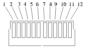
The simplest way is to just open the Scart connector, figure out how the strands are coloured, cut off the Scart connector and solder on the 9pin SUB-D. As I read on various places on the net, though, there is more than one version of the 1084 around. Only some of them actually have 9pin SUB-D connectors, some are equipped with round DIN connectors, for example. A survey of these models can be found on a page taken from the online A4000 hardware guide. As is usual with RGB connections you should not just use any cable but pay a bit of attention to actually use video cable, which means coaxial cable with 75 Ohms longitudinal resistance. And since there are three signals carrying video information, three of these will be of use. There are cables out there consisting of three or more coax strands and additional ground and sync lines. The tricky part is to find out the pin-out of the Playstation A/V connector. To make it unambiguous I defined the pin numbers on the Playstation A/V connector that way: If you look at the connector from the front, where the pins are, cable on the back, leading away from you, pins extending from top, metal half case of connector on bottom, then the pins are numbered from 1 to 12 beginning on the left:
In the table below you can find that precise pin-out alongside the according pins on the Scart connector, the 15pin HD-SUB-D VGA connector (if you've got a Multisync monitor capable of the 15kHz video input) and the 9pin SUB-D connector on the 1084. If you connect the pins 1:1 it will just work. This is actually confirmed and produces a neat, crisp image on the monitor.
|